Device IOs are used to easily map equipment properties with a bit/offset in a message body.
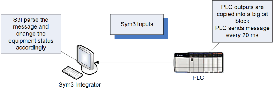
Typically, a Device would 'talk' to Sym3 by sending a message which contains all Device outputs stored in a bitmap.
When using IOs, there is no need to create a new message type with its data type. Sym3 will automatically create the message with the correct length based on the message type ID in the IO table. However, make sure that all message type IDs are unique.
When the Device is first connected, Sym3 will send the initial value for all Sym3 output.
Warning: when sym3 receive a message and apply the binding, the order of bit change is not guarantee.
Example: an input with StartBit = 8 can be changed before an input with StartBit=7
Device IOs are managed in the IO manager.
From the project explorer, double-click on Device IOs.
Device IOs can be created manually in the Device IO grid or imported from either a CSV or TSV file (click on the import button on top of the Device IOs window).
Importing IOs will first erase all existing IO entries.
Device IOs can have a scripting function attached. Refer to Scripting DeviceIO page for examples
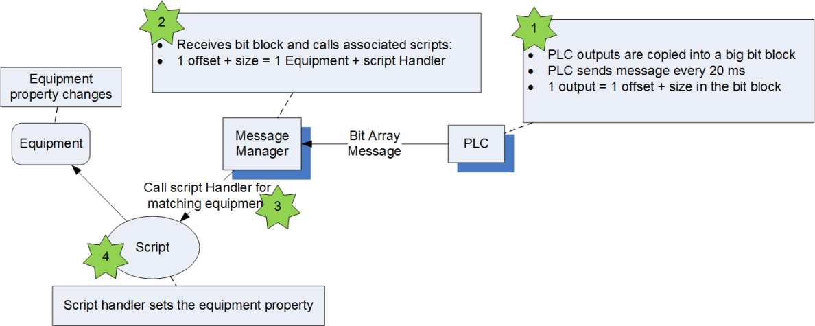
Input IOs are Sym3 inputs (typically a PLC Output like a start/stop output to a conveyor). They map an equipment property to a value in a message body.
The PLC message structure must be:
| Field | Type | Description |
| MessageID | Byte | As defined in the IO table in column Message Type |
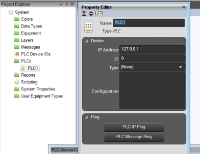
| DeviceID | Byte | Integer value that identifies the device that sent or is to receive message as defined in the PLC Properties
 |
| LocationID | Word | can be ignored for IO messages (set to 0) |
| DeviceRef | Word | can be ignored for IO messages (set to 0) |
| MessageLength | Word | the length of the message body |
| Body | Byte[] | Byte array where each bit is mapped as in the PLC Device IOs table definition in Sym3Note that an IO entry, if coded on more than one bit must not span adjacent 32 bit words |
When the message carrying the PLC Outputs is received by Sym3, the message manager calls the script handlers with the matching equipment as configured in the Device IO. The user must then implement in the script handler what happens to the equipment in Sym3.
Input IO fields:
| Name | Type | Description |
| Equipment Name | String | The name of the equipment |
| Equipment Type | String | The type of the equipment |
| Bit Start Position | Integer | The offset in the message body where the PLC output is mapped |
| Size in Bits | Integer | The number of bits used to code the PLC ouput value |
| Element Size | Integer | Gets the DeviceIO element size. The size in bytes of the data element in the device e.g. 2 bytes is 16 bit WORD. Used for bit field validation and byte swapping for Network byte order systems. |
| Script Handler Function | String | The name of the script handler (written by the user) that will receive the IO value and set the equipment property |
| Identifier | String | Optional for inputs, this value is passed to the script handler. It may be used to specify a specific user defined property name that will hold the input value |
| Input/Output | Integer | Set to 'Input' for input IOs |
| Device Name | String | The name of the Device for receiving this message |
| Message Number | Integer | The message Type number |
| Inverted Logic | Boolean | New in V6.3. Defaults to False. Set this to True if the IO value received should be inverted. This option only affects Boolean values, other types are unaffected |
| Comment | String | New in V6.3. Free form comment (avoid commas) |
| UpdateRate | Integer | Gets the Update rate for the DeviceIO (Output UpdateRate) Only in CSV file |
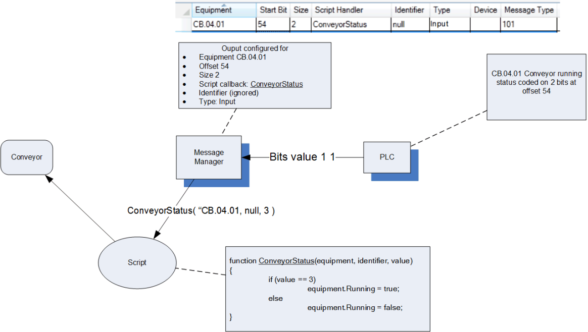
Example: Start/Stop Input for a conveyor. In this example, the Start/Stop input is coded on 2 bits. If both bits are high, Sym3 will set the conveyor to Running. Sym3 will stop the conveyor for any other bit values.
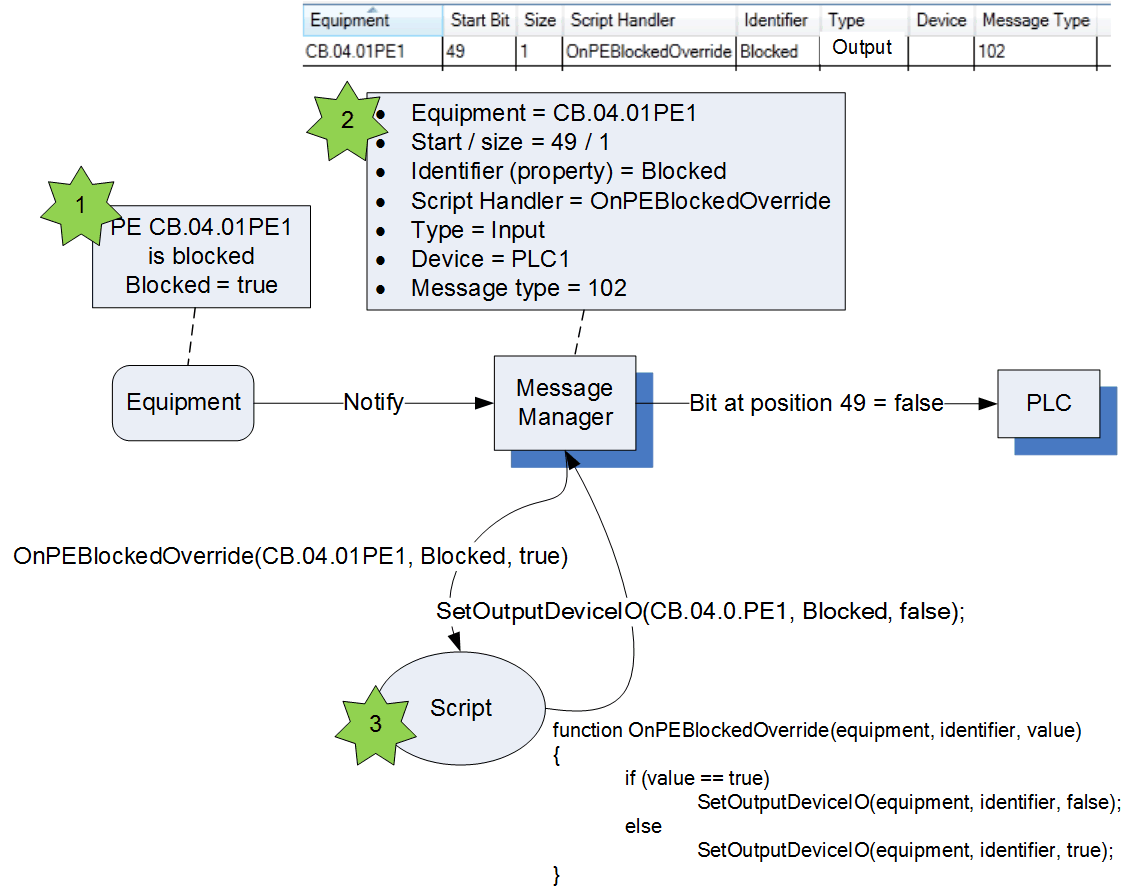
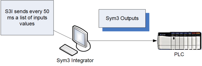
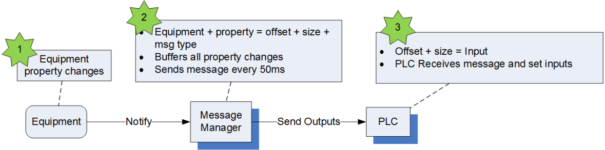
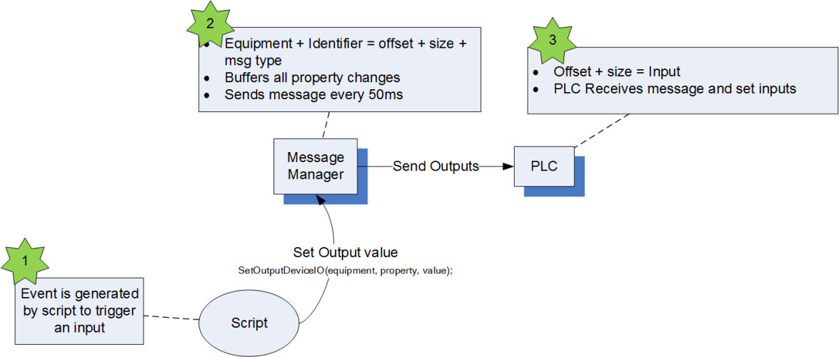
Ouput IOs are Sym3 outputs (typically Sym3 emulate a PE Sensor PLC input). They map an equipment property to a value in a message body.
When the property of an equipment changes, the matching bits in the message are set and the message is sent to the PLC.
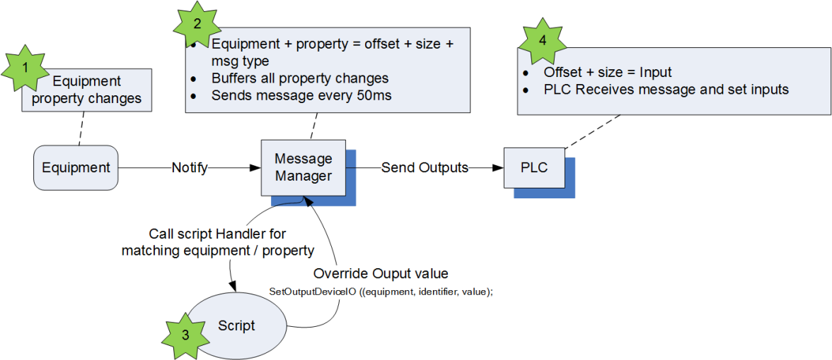
If the bit values can't be directly mapped to the property value, it is possible to intercept the property value change in a script handler, which can then set the Output bit values.
Ouput IO fields:
| Name | Type | Description |
| Equipment Name | String | The name of the equipment |
| Equipment Type | String | The type of the equipment |
| Bit Start Position | Integer | the offset in the message body where the PLC input is mapped |
| Size in Bits | Integer | the number of bits used to code the PLC input value |
| Element Size | Integer | Gets the DeviceIO element size. The size in bytes of the data element in the device e.g. 2 bytes is 16 bit WORD. Used for bit field validation and byte swapping for Network byte order systems. |
| Script Handler Function | String | Optional. The name of the script handler (written by the user) that will receive the equipment property update and manually set the Output bits |
| Identifier | String | The equipment property name or equipment user defined property |
| Type | Integer | Set to 'Output' for output IOs |
| Device Name | String | the name of the Device for sending this message |
| Message Number | Integer | The message Type number |
| Inverted Logic | Boolean | New in V6.3. Defaults to False. Set this to True if the IO value sent should be inverted . This option only affects Boolean values, other types are unaffected |
| Comment | String | New in V6.3. Free form comment (avoid commas) |
| Output UpdateRate | Integer | Default 50 for an output. The rate (milliseconds) for Sym3to poll for changes to this IO |
Setting Inverted Logic does not change the value but does change how it is interpreted. When triggered an 'Output' with inverted logic enabled is treated as an 'Input'
Output IOs can be used in 3 different ways:
First case: In the most simple case, the equipment property is directly mapped to the output. There is no script to write.
Second case: A small script handler converts the equipment property to outputs. This could typically be used to invert the value of a PE sensor blocked/unblocked values.
Note that setting a script handler will intercept the IO changes. The script must handle these changes in order for these properties to change.
Third case: The setting of the Output is triggered by the script (ie. independently of the actual equipment property).
Example:
This example illustrates the case #2 above where a small script handler inverts the PE block value so that a bit HIGH means PE unblocked.